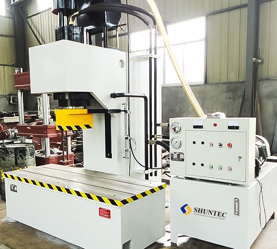
The schematic diagram of the hydraulic press system is drawn with the graphic symbols of the hydraulic components. There are many kinds of hydraulic components, among which the control components are the most. The meaning of the graphic symbols of the control components is of great significance to the analysis and design of the hydraulic press system.
If drawings are the language of engineering, hydraulic press system schematics are the language of hydraulics. The hydraulic press system schematic diagram is a graphic that expresses the working principle of the hydraulic press system with prescribed lines and symbols in order to facilitate reading, analysis, design, and drawing. According to the regulations, the graphic symbols of hydraulic components only represent the function of the component, not the structure and parameters of the component, and are represented by the static state or zero states of the component.
The wide application of hydraulic technology in construction machinery and the rapid development of electromechanical-hydraulic integrated products. From the perspective of hydraulic technology, if you want to do a good job in the design, management, and maintenance of electromechanical-hydraulic integrated equipment, being able to understand the schematic diagram of the hydraulic press system has become a basic skill requirement.


