Understanding stamping press components is essential for anyone involved in metal forming, equipment selection, or production optimization. While many resources explain what a press is, far fewer break down how each component contributes to performance, precision, and long-term reliability.
This guide provides a component-level engineering perspective, helping you understand how structural elements, drive systems, and control modules work together. Whether you are an engineer evaluating equipment or a buyer comparing specifications, this breakdown will help you make more informed decisions.
Overview of Stamping Press Structure
A stamping press is not a single mechanism but a system of coordinated components designed to convert energy into controlled forming force.
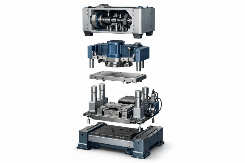
At a high level, the structure can be divided into five functional groups:
- Structural components → provide rigidity and support
- Force generation system → creates and delivers energy
- Slide and motion system → transfers force to tooling
- Die interface components → enable forming operations
- Control and safety systems → regulate and protect operations
Each group directly affects press accuracy, production speed, and operational stability.
Core Structural Components (Frame & Bed)
The structural system defines the foundation of press performance. Even with advanced controls, poor structural integrity will result in misalignment and inconsistent output.
Press Frame
The frame is the main load-bearing structure of the press. Common configurations include:
- C-frame (gap frame) → open front, easier access, lower rigidity
- H-frame (straight-side) → enclosed structure, higher stiffness
Key functions:
- Maintain alignment under load
- Absorb and distribute forming forces
- Minimize deflection during operation
Frame deflection directly impacts part accuracy and die life. High-tonnage applications require rigid, low-deflection designs.
Bed / Bolster Plate
The bed is the stationary base where the lower die is mounted.
Key roles:
- Provides a flat and stable surface
- Supports full load during stamping
- Ensures die alignment with the slide
Critical factors:
- Surface flatness tolerance
- Load distribution capability
- Mounting hole patterns (T-slots)
Tie Rods / Columns
In heavy-duty presses, tie rods or columns reinforce the structure.
- Maintain frame integrity under high loads
- Prevent deformation over time
- Enable uniform load transfer
Force Generation System Components
This system determines how force is generated and delivered, which directly affects tonnage, speed, and forming characteristics.
Flywheel (Mechanical Press)
The flywheel stores rotational energy and releases it during the stamping cycle.
Key benefits:
- Energy efficiency
- Consistent motion
- High-speed operation capability
Crankshaft / Eccentric Drive
This mechanism converts rotational motion into linear motion.
- Drives the slide up and down
- Defines stroke characteristics
- Controls motion profile
Engineering Insight: Crank design affects the tonnage curve, meaning maximum force is only available near the bottom of the stroke.
Hydraulic Cylinder (Hydraulic Press)
In hydraulic systems, force is generated through fluid pressure.
Advantages:
- Full tonnage available at any stroke position
- Adjustable force and speed
- Better control for deep drawing applications
Motor and Drive System
The motor provides the initial energy input.
- Mechanical presses → constant-speed motors
- Advanced systems → variable-speed drives
Slide and Ram Assembly
The slide (or ram) is the primary moving component, responsible for delivering force to the die.
Ram / Slide
- Moves vertically during operation
- Transfers force from the drive system to tooling
- Must maintain strict alignment
Guide Systems (Gibs / Rails)
Guides ensure precise motion by restricting lateral movement.
Functions:
- Maintain vertical alignment
- Reduce vibration
- Improve repeatability
Engineering Insight: Poor guide system design leads to uneven wear, misalignment, and part defects.
Stroke Adjustment Mechanism
Allows operators to adjust:
- Stroke length
- Shut height (distance between slide and bed at bottom dead center)
This flexibility is critical for handling different tooling setups.
Die Interface and Tooling Components
These components directly interact with the material and define the final part quality.
Upper Die Connection
Mounted on the slide:
- Transfers motion to the die
- Must ensure rigid and secure attachment
Lower Die Mounting
Fixed to the bed:
- Provides stable support
- Maintains alignment with upper die
Die Cushion
Used in specific applications like deep drawing:
- Applies upward force
- Controls material flow
- Prevents wrinkling
Quick Die Change Systems
Modern presses often include systems that:
- Reduce setup time
- Improve production efficiency
- Enhance operator safety
Control and Automation Components
Modern stamping presses rely heavily on electronic control systems to ensure precision and repeatability.
Control System (PLC / CNC)
The control system manages:
- Stroke timing
- Speed profiles
- Force application
Sensors and Feedback Systems
Sensors provide real-time monitoring:
- Position sensors → track slide movement
- Load sensors → monitor tonnage
- Temperature sensors → protect system components
Human-Machine Interface (HMI)
The HMI allows operators to:
- Adjust parameters
- Monitor performance
- Diagnose issues
Safety Components in Stamping Press Systems
Safety systems are critical due to the high forces involved.
Light Curtains
- Detect operator intrusion
- Stop press immediately
Emergency Stop Systems
- Provide instant shutdown capability
- Essential for operator protection
Overload Protection
- Prevents damage to press and tooling
- Automatically stops operation under excessive load
Guarding Systems
- Physical barriers to prevent accidental contact
- Required for compliance with safety standards
Common Wear Parts and Maintenance-Critical Components
Not all components wear equally. Some require regular inspection and replacement.
Key wear components include:
- Bushings and bearings → support moving parts
- Guide rails → subject to friction and alignment stress
- Hydraulic seals → prone to leakage over time
- Lubrication systems → essential for reducing wear
Practical Insight: Failure of small components like bearings can lead to major downtime and costly repairs.
How Component Design Affects Press Performance
Each component contributes to overall system performance:
- Frame rigidity → determines accuracy and die life
- Drive system → affects speed and force delivery
- Guide system → controls repeatability
- Control system → ensures process stability
A well-designed press integrates all components into a balanced, optimized system.
Conclusion: Why Component-Level Understanding Matters
Understanding stamping press components goes beyond basic knowledge—it directly impacts production quality, equipment lifespan, and operational efficiency.
By analyzing how each component contributes to force transmission, alignment, and control, you can:
- Identify potential failure points
- Optimize maintenance strategies
- Make better equipment decisions
